Every traction lift needs somewhere to put its machine. An elevator machine room is the dedicated room, usually directly above the lift shaft, that houses the traction machine, the controller and the drive. A machine-room-less (MRL) lift puts the same equipment inside the shaft instead, and has been the default for low and mid-rise buildings since the 2000s. Choosing between them affects floor area, roof height, construction cost, maintenance and the way the lift appears in the building model, so it is one of the first lift decisions to settle on a project.
This guide compares the two on the points that matter at design stage: the space and headroom each needs, the speed and travel limits, the cost and maintenance trade-off, heat and ventilation, and what the BIM model shows for each.
What Is an Elevator Machine Room?
An elevator machine room is a separate, lockable room that contains the hoisting machine, controller, drive and main disconnects for one or more lifts. In traction lifts it usually sits above the shaft; EN 81-20 requires a clear working height of at least 2.1 m inside it.
The machine room is where traction lifts started, and it remains the standard arrangement for tall buildings, fast lifts and heavy-duty installations. The room typically contains electrical disconnects, the controller cabinets, the machine itself and, in many cases, a lifting beam in the ceiling and a floor hatch so heavy parts can be winched in and out.
Because everything is in one place, a machine room makes life easier for the people who maintain the lift. A technician can work on the machine, brake and controller while standing on a solid floor, away from the moving car, and can carry out a rescue by releasing the brake from the room. The trade-off is space: the room adds a structure on the roof, takes area that could otherwise be used, and needs its own ventilation and access route.
Not every machine room sits above the shaft. Bottom-drive traction lifts and hydraulic lifts place the machine room at or near the lowest level, usually next to the shaft. For hydraulic lifts this is the normal arrangement, because the pump unit and tank have to sit close to the cylinder.
What Is an MRL Lift?
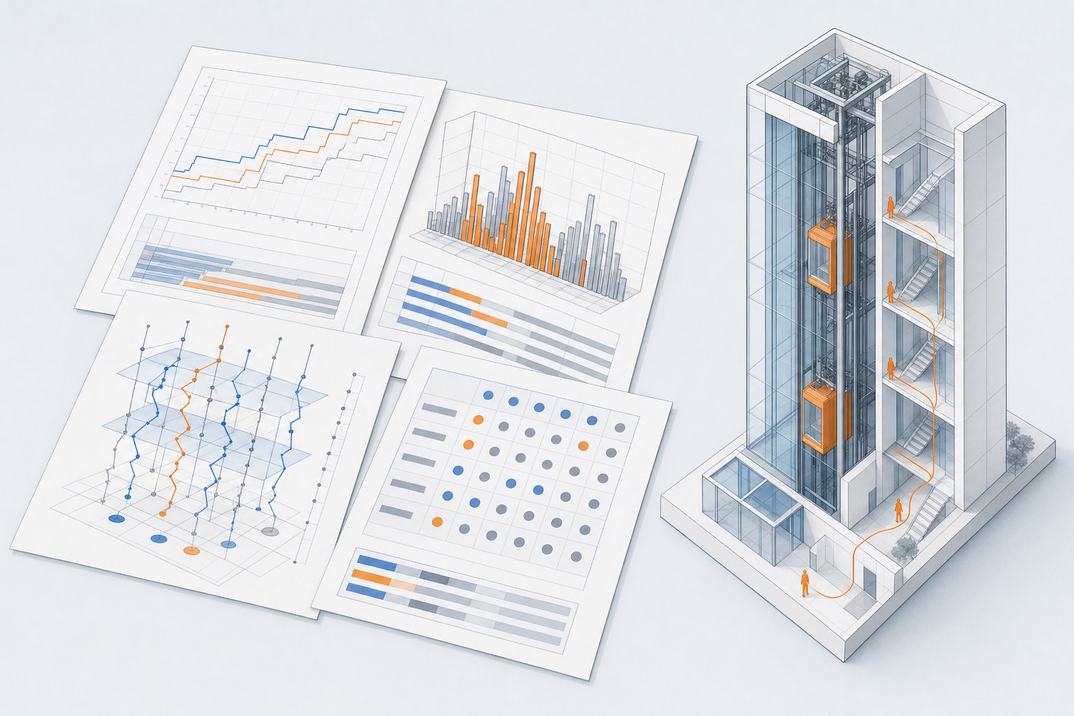
An MRL (machine-room-less) lift is a traction lift whose machine sits inside the shaft, usually at the top on a guide rail or the shaft wall. It removes the need for an elevator machine room. MRL technology spread from the late 1990s and became mainstream in low and mid-rise buildings in the 2000s.
MRL lifts were made possible by compact gearless motors, often using permanent magnet technology, which are small enough to fit in the space between the car and the shaft wall. With the machine in the shaft, the remaining question is where the controller goes. Early designs put it in the shaft headroom, which made it impossible to reach if the car was stuck. Later designs moved it into a landing door frame, which brought problems with overheating and security. Most current MRL lifts use a controller cabinet or a small control room at or near the top landing.
An MRL lift also has an emergency and test panel, normally at the top landing next to the landing door. This is where a technician releases the brake and moves the car during a rescue, without needing to enter the shaft.
Elevator Machine Room vs MRL at a Glance
The core difference is location: an elevator machine room puts the machine and controller in a separate room, while an MRL puts the machine in the shaft and the controller in a cabinet at the top landing. All 6 trade-offs below follow from that single decision.
- Machine and controller location. Machine room: in a dedicated room above or beside the shaft. MRL: machine in the shaft, controller in a landing cabinet or small control room.
- Floor area. Machine room: a room on the roof or top floor, often around the size of the shaft or larger. MRL: no room, only a cabinet or small control space.
- Headroom. Machine room: standard shaft headroom plus the room above it. MRL: a taller shaft head, often about 3.4 m from the top floor.
- Speed and travel. Machine room: suits any speed and travel, including high-rise. MRL: suits low and mid-rise, with typical limits on speed, load and travel.
- Maintenance. Machine room: work from a solid floor, away from the car. MRL: work from the car roof or the pit, with rescue from the landing panel.
- Lifespan. Machine room: usually longer. MRL: some consultants report shorter rope and component life in heavy use.
Each of these points is covered in more detail below.

Space: Elevator Machine Room Size and Clearances
A typical elevator machine room for one traction lift is roughly 3.7 m by 3.7 m (12 ft by 12 ft), including maintenance space, and around 6.1 m by 3.7 m (20 ft by 12 ft) for two. EN 81-20 sets a 2.1 m clear working height and 2.0 m by 0.6 m access doors.
Those room sizes come from US practice, and the real figure always comes from the chosen manufacturer, but they give a sense of scale: a machine room for two lifts takes roughly 20 m² of roof or top-floor area. The main dimensional rules in the European standard are:
- Clear height. EN 81-20 increased the clear height of working spaces in machine rooms to 2.1 m, and of entrances to them to 2.0 m.
- Access doors. Doors into machine rooms and shafts must be at least 2.0 m high and 0.6 m wide; pulley room doors at least 1.4 m by 0.6 m.
- Trapdoors. Where access is through a trapdoor, it must give a clear passage of at least 0.8 m by 0.8 m and be counterbalanced.
In the US, ASME A17.1 requires a clear headroom of at least 7 ft (about 2.13 m) in the machine room, and NFPA 70 sets working clearances in front of the controller and disconnects. In Hong Kong, the Buildings Department code of practice for lifts gives minimum dimensions for the machine room and headroom, with a separate section on MRL installations.
A machine room also needs a safe route to it. If the room floor is more than a small step above or below the access route, stairs or a fixed ladder are needed, and the route should allow replacement parts, including the machine, to be brought in. That usually means a lifting beam above the machine and a clear path to the nearest goods route.
The MRL lift saves almost all of this. What remains is a controller cabinet or control room at the top landing, plus the landing emergency and test panel. In the US, a control room must be adjacent to the shaft and within a set distance of the machine, which one reference gives as 150 ft (46 m).
Headroom and Pit: What Each Option Needs in the Shaft
An MRL lift usually needs more headroom inside the shaft than a machine room lift, because the machine sits at the top. One manufacturer gives a typical standard MRL shaft head of about 3,400 mm from the top finished floor, with reduced-headroom versions available for lighter, slower lifts.
The headroom is the distance from the top landing floor to the underside of the shaft ceiling. In a machine room lift, the machine sits in the room above, so the shaft only needs enough headroom for the car, the refuge space on the car roof and the overrun. In an MRL lift, the shaft head also has to hold the machine, its supports and, in some designs, the governor, so it tends to be taller.
Manufacturers have worked hard to bring this down. Reduced-headroom and reduced-pit options are now common for lifts of up to about 1,000 kg at 1.0 m/s, but they usually come with conditions, such as limits on travel and extra equipment like a telescopic balustrade on the car roof. For existing buildings, some products are designed to fit into the original shaft and leave the old elevator machine room empty for other uses, which can make an MRL a good modernisation option.
EN 81-20 also sets the refuge spaces that must be available above the car and in the pit, so that a technician cannot be crushed. These apply to both arrangements, but they matter more for MRL lifts because maintenance happens inside the shaft. The refuge on the car roof must be at least 0.4 m by 0.5 m by 2.0 m high for a standing position, or 0.5 m by 0.7 m by 1.0 m high for a crouching position.
The pit depth depends mainly on speed and buffer type rather than on where the machine is, so it is often similar for both options. The shaft plan, headroom and pit for any lift are set out in more detail in our guide to lift shaft dimensions.

Speed, Load and Travel Limits
MRL lifts suit low and mid-rise buildings, with typical published ranges of up to about 1.6 to 2.5 m/s and 75 m of travel, depending on the product. An elevator machine room has no such ceiling and remains the usual choice for faster, taller and heavier lifts.
The limits come from the size of the machine. To fit inside the shaft, the motor has to be compact, which caps the torque it can deliver and therefore the load, speed and travel it can handle. Manufacturers state these limits product by product. Some examples from published data:
- Small residential MRL. One compact product for low-rise residential buildings is offered at 630 kg, 0.5 to 1.0 m/s and up to 15 floors.
- General-purpose MRL. Another product range offers loads up to 1,600 kg at 1.6 to 1.75 m/s, with travel of up to 75 m.
- Larger MRL. Some references describe MRL lifts at up to 500 ft per minute (about 2.5 m/s) and 250 ft (about 76 m) of travel.
Beyond these limits, a machine room is the normal answer. High-rise passenger lifts at 4 m/s and above, double-deck lifts, heavy goods lifts and large firefighting or bed lifts often need machines that are too big for the shaft. If a building is near the top of an MRL range, check whether a future increase in floors or loads would push it over, and see our guide to lift planning for high-rise buildings.
Cost: Capital, Space and Lifetime
An MRL lift usually costs less to build than a machine room traction lift, mainly because it saves the room and its structure. One US consultant puts a traditional traction lift at about 50% more than a hydraulic lift, and an MRL at within about 10% of a hydraulic lift.
Those figures are US and relative, not a price list, but they show where the savings come from. A machine room is a piece of building: a roof structure, walls, a fire-rated enclosure where required, a door, lighting, ventilation, a lifting beam and an access route. Removing it saves construction cost and frees space that can be used for something else, which in offices and apartments can be valuable in its own right.
The lifetime picture is less clear-cut. The same consultant reports that ropes or belts on MRL lifts may need replacing about every 5 years, compared with 8 to 10 years for traditional ropes, and quotes a 15 to 20-year life for MRL lifts against 20 to 30 years for traditional traction or hydraulic lifts. He advises against MRLs in very high-usage or harsh environments, and against replacing a 15 or 20-storey traditional traction installation with an MRL, because the up-front savings may not cover the extra maintenance and modernisation. These are one author’s observations, not industry averages, but they are a useful prompt to look at whole-life cost rather than the tender price alone.
Energy use can be similar for modern gearless lifts of either kind, since both now use efficient permanent magnet machines and variable frequency drives, often with regenerative drives that return energy to the building. The difference is that a machine room may need its own cooling, which adds running cost. For the cost of replacing or modernising existing lifts, see our guide to lift modernisation cost.

Maintenance, Access and Rescue
An elevator machine room gives technicians an enclosed space with at least 2.1 m of clear working height, away from the moving car. On an MRL, maintenance is done from the car roof or the pit, and one consultant notes that downtime can be much longer when something goes wrong in the shaft head.
The practical differences are:
- Working position. In a machine room, the technician works on a fixed floor. On an MRL, most work on the machine is done from the car roof, using the refuge spaces and balustrade that EN 81-20 requires.
- Rescue. In a machine room, a trapped car can be moved by releasing the brake at the machine. On an MRL, the same is done from the emergency and test panel at the landing, which needs a secure but accessible location.
- Replacement parts. In a machine room, the machine can be lifted out with the beam and hatch. On an MRL, removing a machine from the shaft head needs more planning, and the car or a platform may be needed as a working base.
- Proprietary equipment. MRL designs differ more between manufacturers than traditional machine room lifts, so check that parts and service will be available from more than one contractor over the life of the lift.
For lifts in busy public buildings, hospitals and transport hubs, where availability matters most, these points often tip the decision towards a machine room even when an MRL could carry the load.
Heat, Ventilation and Environment
Both arrangements need the machine and controller kept within the manufacturer’s temperature range. One US state code sets a default of 13°C to 38°C (55°F to 100°F) where no manufacturer range is given, which an elevator machine room achieves with ventilation or cooling.
A machine room is easier to control. It has a defined volume, a door and walls, so it can be ventilated, heated or air-conditioned to suit the equipment. US codes typically require dedicated ventilation or cooling for machine rooms and control rooms, independent of other building systems, to protect the electrical equipment from overheating.
An MRL relies on the shaft. In most buildings the shaft temperature is stable, but heat from the machine and drive collects at the top, and a shaft on an external wall, near a glazed atrium or in an unheated building can get too hot or too cold. One consultant reports controller problems in extreme cold and corrosion from moisture in some MRL installations. If the shaft is exposed, check the manufacturer’s limits and ask the building services engineer to confirm the shaft temperature in summer and winter.
What the BIM Model Shows for Each Option
A lift BIM model should show the shaft, headroom and pit for both options, plus either the elevator machine room with its access, hatch and lifting beam, or the MRL controller cabinet and landing panel. Getting these right at RIBA Stage 2 or 3 avoids clashes later.
The model matters because the two options affect different trades. An elevator machine room changes the roof: the structural engineer needs the room, the lifting beam and the machine loads; the architect needs the room, door and access route; and the building services engineer needs the ventilation and power. An MRL changes the shaft: the headroom is taller, the machine loads sit on the rails or shaft walls, and the top landing needs space for the controller cabinet and the emergency panel.
A useful lift model at design stage includes:
- Shaft. Width, depth, headroom and pit, with clear zones for the car, counterweight and doors.
- Machine room or MRL space. The room footprint, clear height, door and hatch for a machine room; or the shaft head equipment zone, controller cabinet and landing panel for an MRL.
- Loads. The reactions on the slab, beams, rails or walls, as data the structural engineer can use.
- Access. The route to the machine room or the control space, for maintenance and replacement.
- Data. Load, speed, travel and the number of stops, so the model stays linked to the traffic design.
AdSimulo’s lift design software generates lift design BIM files in IFC format from the lift configuration you design, so the model follows the traffic analysis rather than being drawn separately. See our page on elevator BIM models for what the output includes.
How to Choose Between an Elevator Machine Room and an MRL
Choose an MRL for most low and mid-rise buildings of up to about 20 floors with standard loads and speeds of up to about 1.6 to 2.5 m/s. Choose an elevator machine room for high-rise, fast or heavy lifts, and where availability and easy maintenance matter more than space.
A simple way to decide is to work through these questions in order:
- Do the speed, load and travel fit an MRL? Check the manufacturer’s limits. If the traffic design needs faster or larger lifts than an MRL range allows, a machine room is needed.
- Is there headroom for an MRL? If the shaft head is restricted, for example by a planning height limit or an existing roof, check reduced-headroom products or consider a machine room beside the shaft.
- How heavily will the lift be used? For busy public buildings, hospitals and transport, weigh the easier maintenance of an elevator machine room against the space saving.
- What is the space worth? In a dense city centre scheme, the roof or top-floor area saved by an MRL may be worth more than the lift itself.
- Is this a new building or a modernisation? In an existing building, an MRL can sometimes fit the old shaft and free the old elevator machine room, but the shaft and headroom must be surveyed first. Our guide to lift modernisation traffic analysis explains how to check that the new lifts will still meet demand.
Whichever option you choose, the traffic design comes first: it sets the number, size and speed of the lifts, and those set whether an MRL is possible at all. The safety rules for both arrangements are covered in our guide to lift and elevator standards, and the European requirements for machine rooms and refuge spaces are summarised in NBS’s guide to EN 81-20 and EN 81-50.